8. Control Panel
PC-BSD® provides a Control Panel which contains tools for managing your system. The Control Panel is available from any desktop, meaning it is available regardless of which desktop you log into.
Note
if a desktop does not contain an icon or menu item for Control Panel, type pc-controlpanel from a shell prompt to launch the Control Panel.
A screenshot of Control Panel started from the KDE desktop can be seen in Figure 8.1: PC-BSD® Control Panel.

The available utilities are divided into sections. If you click a grey section bar, you can toggle between displaying (bar has up arrow) or hiding (bar has down arrow) its icons.
The search box in the upper right can be used to find the proper control panel item if you know what you would like to configure but are uncertain which utility to use. The icon next to the search box can be used to change the size of the icons, change the view from a grid to a list, and organize the icons into a fixed layout.
If an icon includes a yellow exclamation mark, you will need to input your password in order to access that configuration utility.
Note
if your user account is not a member of the wheel group, you will not see the configuration utilities in Control Panel that require a password. By default, the first user account that you create is made a member of the wheel group. You can log in as that user and use User Manager to add other accounts to this group.
Control Panel includes a “desktop selector” menu which allows you to load the configuration utilities from just the operating system (as seen in the example in Figure 8.1: PC-BSD® Control Panel), all installed desktops, or one of these installed desktops: KDE, GNOME, Cinnamon, MATE, XFCE4, LXDE, or Lumina. In the example shown in Figure 8.2: Desktop Selector Menu, the user is currently logged into the LXDE desktop but they have chosen to view the GNOME utilities. The menu icon indicates the control panel view while “(current)” will be beside the desktop that is presently active.

Switching between the icons in the selector changes the icons displayed within the control panel window to match those used in that desktop. If “All desktops” is set by the desktop selector, you will see every utility that is available, depending upon which desktops are currently installed. You can change which desktops are installed using AppCafe®.
The following utilities are found in the Control Panel of a PC-BSD® system, regardless of which desktops are installed:
System management
- About
- Active Directory & LDAP
- Hardware Compatibility
- Login Manager
- Service Manager
- System Manager
- User Manager
Hardware
Networking
Tools
This chapter describes these utilities in more detail.
8.1. About
The “About” icon of Control Panel can be used to quickly find information about the PC-BSD® system. To start the application, double-click its icon in Control Panel or type about-gui. An example is seen in Figure 8.1.1: About Information.
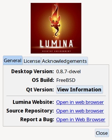
he displayed information includes the version of PC-BSD®, whether the system is using the PRODUCTION, EDGE, or ENTERPRISE package set, the hostname of the system, the underlying version of FreeBSD, the architecture, the name of the kernel (ident), the type of CPU, and the amount of installed memory.
If you click the “Software and system components” button, the screen shown in Figure 8.1.2: System Components Screen will be displayed.

Click the arrow next to an entry to display or hide its its details. The following information is available:
- Video stack: the Xorg version number, the type and version of the loaded video driver, and the version of the loaded VirtualBox driver.
- Toolkits: the version numbers for the installed graphical toolkits.
- Desktops: the version numbers of each installed desktop environment.
- Office: if an office suite is installed, its version number.
- Scripting languages: the version numbers of any installed scripting languages, such as Perl or Python.
8.2. Active Directory & LDAP
The “Active Directory & LDAP” icon is used for managing connections to an Active Directory or OpenLDAP domain. If your network contains an Active Directory or OpenLDAP server, use this icon to input the settings needed to connect to your account information stored on the network.
This utility is to manage the settings of the client, not the Active Directory or OpenLDAP server itself. This application also needs more testing from users. If you have trouble using this utility or find a bug, please post the details using the Report a bug tool.
To start the application, double-click its icon in Control Panel or type pc-su pc-adsldap. You will be prompted to input your password. Figure 8.2.1: Initial Active Directory & LDAP Screen shows the configuration utility with the Active Directory tab open.

Note
to prevent “DNS Update for localhost.pcbsd-3881 failed: ERROR_DNS_UPDATE_FAILED” errors, set the PC-BSD® hostname to include the realm name. For example, if the current hostname is “pcbsd-3881” and the realm name is “maloney.local”, change the hostname to “pcbsd-3881.maloney.local” in .
If you need to connect to a network running Active Directory, check the box “Enable Active Directory”. This will change the greyed-out status of the rest of the screen, allowing you to configure the following:
- Domain Name (DNS/Realm-Name): input the name of the Active Directory domain (e.g. example.com) or child domain (e.g. sales.example.com). This setting is mandatory.
- NetBIOS Name: input the hostname of the PC-BSD® system as listed in the About icon.
- Workgroup Name: input the name of the Windows workgroup. Unless the administrator has changed it, the default workgroup name is WORKGROUP.
- Allow Trusted Domains: only check this box if the network has active domain/forest trusts.
- Administrator Name: input the name of the Active Directory Administrator account.
- Administrator Password: input and confirm the password for the Active Directory Administrator account.
The values that you input using this GUI are saved to /usr/local/etc/pc-activedirectory.conf and /usr/local/etc/smb4.conf.
Note
once you enable AD, you can no longer configure auto login in Login Manager as users will now authenticate with the Active Directory server.
Figure 8.2.2: Managing LDAP Client Settings shows the configuration utility with the LDAP tab open.

If you need to connect to a network which contains a configured LDAP server, check the box “Enable LDAP”. This will change the greyed-out status of the rest of the screen, allowing you to configure the following:
- Hostname: input the hostname or IP address of the OpenLDAP server. This setting is mandatory.
- Base DN: input the top level of the LDAP directory tree to be used when searching for resources (e.g. dc=test,dc=org).
- Allow Anon Binding: only check this box if the LDAP server allows read and write access without requiring authentication.
- Root bind DN: input the name of the administrative account on the LDAP server (e.g. cn=Manager,dc=test,dc=org).
- Root bind password: input the password for the “Root bind DN”.
- Password Encryption: select a type supported by the LDAP server, choices are: “clear” (unencrypted), “crypt”, “md5”, “nds”, “racf”, “ad”, or “exop”.
- User Suffix: this setting is optional and is usually a department or company name. The input value will be added to the name when a user account is added to the LDAP directory
- Group Suffix: this setting is optional and is usually a department or company name. The input value will be added to the name when a group is added to the LDAP directory.
- Password Suffix: this setting is optional. The input value will be added to the password when a password is added to the LDAP directory.
- Machine Suffix: this setting is optional and usually represents a description such as server or accounting. The input value will be added to the name when a system is added to the LDAP directory.
- Encryption Mode: choices are “NONE”, “SSL”, or “TLS”. The selected type must be supported by the LDAP server.
- Self Signed Certificate: used to verify the certificate of the LDAP server if SSL connections are used. Paste the output of the command openssl s_client -connect server:port -showcerts.
- Auxiliary Parameters: ldap.conf(5) options, one per line, not covered by other options in this screen.
The values that you input into this tab are saved to /usr/local/etc/pc-ldap.conf.
If you are new to LDAP terminology, you may find it useful to skim through the OpenLDAP Software 2.4 Administrator’s Guide.
8.3. Hardware Compatibility
The PC-BSD® installer allows you to quickly determine if your system’s video card, Ethernet card, wireless device, and sound card are compatible with PC-BSD®.
A “Hardware Compatibility” icon in Control Panel provides a quick overview of the system’s detected hardware. To start the application, double-click its icon in Control Panel or type pc-sysinstaller -checkhardware.
In the example shown in Figure 8.3.1: Sample Hardware Compatibility, this system has a detected NVIDIA video card with a configured resolution of 1600x900, one Ethernet device using the em(4) driver, and one wireless device using the iwn(4) driver. Currently no sound card is detected, meaning that the user should configure and test their sound card using the instructions in PC-BSD Mixer Tray.
Hardware that is currently incompatible may show with a green checkbox after a system upgrade or update. This indicates that the update added the driver for the device.

8.4. Login Manager
A Login Manager utility is available in Control Panel. Figure 8.4.1: Login Manager shows the initial screen when you click on this icon in Control Panel or type pc-su pc-dmconf at the command line. Note that this utility will prompt you for your password.

For security reasons, PC-BSD® defaults to a login screen. This means that users are required to input their password before logging into the PC-BSD® system. If you are the only user on the PC-BSD® computer, always use the same window manager, and do not consider it a security risk for the system to automatically boot into that window manager, you can enable auto-login using the “Auto login” tab.
As seen in the example in Figure 8.4.1: Login Manager, the “Enable auto login” box is unchecked by default. If you check the box, the “Auto login user” drop-down menu will be activated. Select the user account to automatically login as. If desired, the “Time Delay” can be changed to control how long the login manager will wait for the user to cancel the automated login. Do not set this setting too low if there are times that you wish to login as a different user or to select a different desktop. When finished, click “Apply” and you will be prompted to input the selected user’s password.
Note
this change requires a reboot. Once the system is rebooted, a login screen will no longer appear unless the user interrupts the automatic boot or until this setting is changed again in Login Manager.
The “Remote login” tab, shown in Figure 8.4.2: Configuring Remote Login, is used to enable a remote user to connect to a desktop session using Virtual Network Computing (VNC). Check the “Enable Remote Desktop (VNC)” box to enable this service. When you click “Apply”, you will be prompted for your password as well as the remote login password to use for the VNC session. Reboot in order to activate the VNC service over port 5900. You will also need to open TCP port 5900 using Firewall Manager. You can test the connection using the “vnc” option of KRDC (shown in Figure 9.6.1: Creating a Connection Using KRDC) or from another VNC client.

Warning
use extreme caution when enabling this option as it makes your system available to anyone over the network. There is an additional risk when a user logs in over VNC as their password is sent in clear text. If you need someone to access your PC-BSD® system to assist with troubleshooting, consider using Remote Desktop instead, which allows you to send an invitation to connect. Always disable any type of remote login immediately after finishing your troubleshooting session. If you are instead using this option to login to your desktop from a remote location such as work or school, configure your network’s firewall to only allow VNC connections from the specific IP address you will be using to make the connection.
The “Misc” tab is shown in Figure 8.4.3: Miscellaneous Options.

This screen provides the following options:
Enable “show password” button: by default, when a user types their password at the login prompt shown in Figure 4.8.1: Optional Services, “*” characters are displayed as the password is typed in order to prevent another user from seeing the password as it is typed. When the “Enable “show password” button” box is checked, and the user clicks the lock icon next to the typed password in the login screen, the asterisks will change to reveal the password.
Allow Stealth Sessions: if this box is checked, a “Stealth Session” checkbox is added to the login menu, as seen in Figure 8.4.4: Logging Into a Stealth Session. When a user logs into a stealth session, meaning that they check the “Stealth Session” box in the login menu, a temporary, encrypted zvol is created, mounted, and used as a temporary home directory. When the user logs out, the zvol is destroyed, along with the contents of that temporary home directory. This allows a user to temporarily use a PC-BSD® system without leaving any data from their login session on the PC-BSD® system. This can be useful, for example, to allow a publicly accessible system to support multiple, transient users. It also allows you to login and run applications as if on a fresh system each time. Should the system be rebooted before you logout of the stealth session, the one-time key is lost, rendering the data useless. A stealth session is similar to a web browser’s private mode, except for your entire desktop session.
Warning
if you log into a stealth session, do not save any data to your home directory as it will be destroyed at logout. If your intent is to safely interact with a PC-BSD® system while retaining the data in your home directory, use PersonaCrypt instead.
Display available users: by default, the list of available users is displayed in the login screen. To hide this list and force the user to input their username, uncheck this box. For security reasons, the Login Manager will refuse logins from the root and toor accounts.
Allow Valid Users with UID under 1000: check this box if you have imported existing users with a UID under 1000, for example from a Solaris NIS server. Checking this box will activate the “Additional Excluded Users” field. You can then use the “+” icon to add an existing user to the exclude list. To remove a user from the exclude list, highlight their entry and click the “-” icon.

8.5. Service Manager
Service Manager, seen in Figure 8.5.1: Managing Services Using Service Manager, provides a graphical utility for managing PC-BSD® services.

Buttons make it easy to start, stop, or restart services and to set the highlighted service to be enabled or disabled whenever the system boots. To access this utility, go to PC-BSD® or type pc-su pc-servicemanager. You will be prompted for your password.
By default, services will be listed alphabetically. You can reorder the services by clicking on the “Service Name”, “Running”, or “Enabled” headers. Service
Manager is a graphical front-end to the rc scripts located in /etc/rc.d.
If you do not know what a service does, do not change its settings in Service Manager. If you would like to learn more about a service, try seeing if there is a man page for it. For example, type man apm or man bootparamd. If a man page does not exist, try seeing what man pages are associated with that keyword. For example:
apropos accounting
ac(8) - connect time accounting
acct(2) - enable or disable process accounting
acct(5) - execution accounting file
accton(8) - enable/disable system accounting
ipfw(4) - IP packet filter and traffic accounting
pac(8) - printer/plotter accounting information
pam_lastlog(8) - login accounting PAM module
sa(8) - print system accounting statistics
8.6. System Manager
This section describes the various tasks that can be performed using the graphical System Manager utility. System Manager can be accessed from or by typing pc-su pc-sysmanager. You will be prompted to input your password.
The “General” tab, shown in Figure 8.6.1: General Tab of System Manager Utility, displays the following system information:
- the version numbers for the PC-BSD® base and its command-line and graphical utilities
- the version of the underlying FreeBSD base
- the CPU type and speed
- the amount of physical memory

The “Generate” button can be used to create a report that includes the following items:
- a listing of the installed components and their versions
- the output of the dmesg command, which shows messages from the kernel
- the last few lines of the
/var/log/messageslog file - the output of the pciconf -lv command, which lists all the devices that were found when the system booted
- your X configuration file, which shows your display settings
- your
/etc/rc.conffile, which shows your startup settings - your
/boot/loader.conffile, which shows which drivers are loaded at boot time - the output of the command df -m, which shows your amount of free disk space
- a listing from the top command, which shows the currently running processes
When you click the “Generate” button, you will be prompted to input the name and location of the text file that will be created. Since it is a text file, you can view its contents in any text editor. When troubleshooting your system, this file is handy to include when you Report a bug.
During the installation of PC-BSD® you had an opportunity to install FreeBSD source and ports. If you did not and wish to do so after installation, use the “Tasks” tab of System Manager, shown in Figure 8.6.2: Tasks Tab of the System Manager Utility.

This tab provides a graphical interface for installing system source or the ports tree using git.
If you click the “Fetch PC-BSD System Source” button, a pop-up menu will display the download process. The source will be saved to /usr/src/. Once the
download is complete, a “Finished!” message will appear and you can click the “Close” button to exit this screen.
If you click the “Fetch PC-BSD Ports Tree” button, a message will indicate that ports are being fetched and will indicate when this is complete by adding a
“Finished!” message to the lower left corner of the message. Ports will be installed to /usr/ports/.
The “Misc” tab of System Manager is seen in Figure 8.6.3: Misc Tab of the System Manager Utility.

This tab contains a checkbox to “Force IBUS keyboard input”. Check this box if you wish to to input Chinese, Japanese, Korean or Indic characters using a Latin keyboard.
8.7. User Manager
The PC-BSD® User Manager utility allows you to easily add and delete users and groups, as well as change a user’s or the administrative password. To access this utility, go to or type pc-su pc-usermanager. You will need to input your password in order to access this utility.
8.7.1. Managing User Accounts
In the example shown in Figure 8.7.1: Viewing User Accounts in User Manager, the system has two user accounts. The dru account has the ability to become the superuser as the “Can administrate system” checkbox is checked.

If you click the “Remove” button for a highlighted user, a pop-up menu will ask if you would like to also delete the user’s home directory (along with all of their files). If you click “No”, the user will still be deleted but their home directory will remain. If you have only created one user account, the “Remove” button will be greyed out as you need at least one user to be able to login to the PC-BSD® system.
Note
while a removed user will no longer be listed, the user account will not actually be deleted until you click the “Apply” button. A pop-up message will indicate that you have pending changes if you close User Manager without clicking “Apply”. If you change your mind, click “No” and the user account will not be deleted; otherwise, click “Yes” and the user will be deleted and User Manager will close.
The password for any user can be changed by first highlighting the user name then clicking the “Change Password” button. You will not be prompted for the old password in order to reset a user’s password; this can be handy if a user has forgotten their password and can no longer log into the PC-BSD® system. If you click the “Change Admin Password” button, you can change the root user’s password.
If you click the “Advanced View” button, this screen will change to show all of the accounts on the system, not just the user accounts that you created. An example is seen in Figure 8.7.2: Viewing All Accounts and Their Details.

The accounts that you did not create are known as system accounts and are needed by the operating system or installed applications. Do not delete any accounts that you did not create yourself as doing so may cause a previously working application to stop working. “Advanced View” provides additional information associated with each account, such as the user ID number, full name (description), home directory, default shell, and primary group. System accounts usually have a shell of nologin for security reasons, meaning that an attacker can not try to login to the system using that account name.
Figure 8.7.3: Creating a New User Account shows the add user account creation screen that opens when you click the “Add” button.

Note
if you click the “Add” button while in “Simple View”, you will only be prompted to enter the username, full name, and password.
This screen is used to input the following information when adding a new user or system account:
Full Name: this field provides a description of the account and can contain spaces. If it is a user account, use the person’s first and last name. If it is a system account, input a description to remind you which application uses the account.
Username: the name the user will use when they log in to the system; it is case sensitive and can not contain any spaces. If you are creating a system account needed by an application, use the name provided by the application’s installation instructions. If the name that you choose already exists as an account, it will be highlighted in red and the utility will prompt you to use another name.
Home Directory: leave this field empty for a user account as the system will automatically create a ZFS dataset for the user’s home directory under
/usr/home/username. However, if you are creating a system account it is important to override this default by typing in /var/empty or
/nonexistent unless the application’s installation instructions specify that the account needs a specific home directory.
Shell: this drop-down menu contains the shells that are available to users when they are at a command prompt. You can either keep the default or select a shell which the user prefers.
UID: by default, the user will be assigned the next available User ID (UID). If you need to force a specific UID, you can set it here. Note that you cannot set a UID lower than 1001 or specify a UID that is already in use by another user account.
Primary Group: if you leave the default button of “New Group” selected, a group will be created with the same name as the user. This is usually what you want unless you are creating a system account and the installation instructions specify a different group name. Note that the drop-down menu for specifying a group name will only show existing groups, but you can quickly create a group using the “Groups” tab.
Password: the password is case-sensitive and needs to be confirmed.
Once you have made your selections, press the “Save” button to create the account.
8.7.2. PersonaCrypt
Beginning with 10.1.2, PC-BSD® provides support for PersonaCrypt. A PersonaCrypt device is a removable USB media, such as a USB stick, which has been formatted with ZFS and encrypted with GELI. This device is used to hold a specific user’s home directory, meaning that they can securely transport and access their personal files on any PC-BSD® 10.1.2 or higher system. This can be used, for example, to securely access one’s home directory from a laptop, home computer, and work computer. The device is protected by an encryption key and a password which is, and should be, separate from the user’s login password.
Note
when a user is configured to use a PersonaCrypt device, that user can not login using an unencrypted session on the same system. In other words, the PersonaCrypt username is reserved for PersonaCrypt use. If you need to login to both encrypted and unencrypted sessions on the same system, create two different user accounts, one for each type of session.
PersonaCrypt uses GELI’s ability to split the key into two parts: one being your passphrase, and the other being a key stored on disk. Without both of these parts, the media cannot be decrypted. This means that if somebody steals the key and manages to get your password, it is still worthless without the system it was paired with.
Warning
USB devices can and do eventually fail. Always backup any important files stored on the PersonaCrypt device to another device or system.
Advanced Mode can be used to initialize a PersonaCrypt device for any created user, except for the currently logged in user. In the example shown in Figure 8.7.4: Initialize PersonaCrypt Device, a new user, named dlavigne, has been created and the entry for that user has been clicked.

Before a user is configured to use PersonaCrypt on a PC-BSD® system, two buttons are available in the “PersonaCrypt” section of “Advanced Mode”. Note that this section is hidden if the currently logged in user is selected. Also, if you have just created a user and do not see these options, click “Apply” then re-highlight the user to display these options:
- Import Key: if the user has already created a PersonaCrypt device on another PC-BSD® system, click this button to import a previously saved copy of the key associated with the device. Once the key is imported, the user can now login to this computer using PersonaCrypt.
- Initialize Device: used to prepare the USB device that will be used as the user’s home directory.
To prepare a PersonaCrypt device for this user, insert a USB stick and click “Initialize Device”. A pop-up menu will indicate that the current contents of the device will be wiped and that the device must be larger than the user’s current home directory.
Warning
since the USB stick will hold the user’s home directory and files, ensure that the stick is large enough to meet the anticipated storage needs of the home directory. Since the stick will be reformatted during the initialization process, make sure that any current data on the stick that you need has been copied elsewhere. Also, the faster the stick, the better the user experience while logged in.
Press “OK” in the pop-up menu. This will prompt you to input and confirm the password to associate with the device. Another message will ask if you are ready. Click “Yes” to initialize the device. The User Manager screen will be greyed out while the device is prepared. Once the initialization is complete, the User Manager screen will change to display the device’s key options, as seen in Figure 8.7.5: PersonaCrypt Key Options.

The following options are now available:
- Export Key: used to create a copy of the encryption key so that it can be imported for use on another PC-BSD® system.
- Disable Key (No Data): used to uninitialize the PersonaCrypt device on this system. Note that the device can still be used to login to other PC-BSD® systems.
- Disable Key (Import Data): in addition to uninitializing the PersonaCrypt device on this system, copy the contents of the user’s home directory to this system.
Once a user has been initialized for PersonaCrypt on the system, their user account will no longer be displayed when Logging In unless their PersonaCrypt device is inserted. Once the USB device is inserted, the login screen will add an extra field, as seen in the example shown in Figure 4.8b.
Note
if the “Allow Stealth Sessions” checkbox has been checked in , PersonaCrypt users will still be displayed in the login menu, even if their USB device is not inserted. This is to allow those users the option to instead login using a stealth session. See Login Manager for more information about stealth sessions.
In the field with the yellow padlock icon, input the password for the user account. In the field with the grey USB stick icon, input the password associated with the PersonaCrypt device.
Warning
To prevent data corruption and freezing the system DO NOT remove the PersonaCrypt device while logged in! Always log out of your session before physically removing the device.
8.7.3. Managing Groups
If you click the “Groups” tab, you can view all of the groups on the system, as seen in Figure 8.7.6: Managing Groups Using User Manager.

This screen has 3 columns:
Groups: shows all of the groups on the system.
Available: shows all of the system and user accounts on the system in alphabetical order.
Members: indicates if the highlighted group contains any user accounts.
To add an account to a group, highlight the group name in the “Groups” column. Then, highlight the account name in the “Available” column. Click the right arrow and the selected account will appear in the “Members” column. You should only add user accounts to groups that you create yourself or when an application’s installation instructions indicate that an account needs to be added to a group.
If you click the “Add” button, a pop-up menu will prompt you for the name of the new group. Once you press “OK”, the group will be added to the “Groups” column.
If you click the “Remove” button, the highlighted group will automatically be deleted after you press the “Apply” button, so be sure to do this with care. Again, do not remove any groups that you did not create yourself or applications that used to work may stop working.
8.8. Disk Manager
The PC-BSD® Disk Manager can be used to manage ZFS pools and datasets as well as the disks attached to the system. To access this utility, use or type pc-su pc-zmanager from within an xterm. You will need to input your password in order to access this utility.
As seen in the example in Figure 8.8.1: Viewing the System’s ZFS Datasets, the utility will open in the “ZFS Filesystems” tab and will display the system’s ZFS datasets and their snapshots, the amount of space available to each dataset, and the amount of space each dataset is using.

The name of the pool in this example is tank1. If the system has multiple pools, click the green arrow to select the desired pool.
If you right-click the pool name under “Filesystems”, the following options are available:
- Mount: whether or not the filesystem can be mounted depends upon the value of the “canmount” property of the dataset.
- Create new dataset: Figure 8.8.2: Creating a New ZFS Dataset shows the options that are available when you create a new dataset.
- Create a clone dataset: creates a copy of the dataset.
- Take a snapshot: will prompt for the name of the snapshot. The field is pink to remind you to type the snapshot name in immediately after the pool name and @ symbol. In this example, tank1@ will be displayed in the name field. An example snapshot name could be tan1k@snapshot1 or tank1@201505181353 to denote the date and time the snapshot was created. The snapshot creation will be instantaneous and the new snapshot will be added to the list of datasets and will have a camera icon. Click the entry for the snapshot entry if you wish to rename it, clone it, destroy it, rollback the system to that point in time, or edit its properties. If you forget when you made the snapshot, pick “Edit properties” from the snapshot’s right-click menu as it will show its “creation” property.
- Edit properties: allows you modify the ZFS properties for the pool, as seen in the example shown in Figure Figure 8.8.3: Editing the Pool’s ZFS Properties. The available options depend upon the property being modified. The options which are read-only will have a red minus sign icon next to them. ZFS options are described in man zfs and you should not change any options unless you are familiar with the ramifications of doing so.


When creating a new dataset or clone, the following options are available. Again, these options are described in man zfs and you should not change any options unless you are familiar with the ramifications of doing so.
- Name: this field is pink as a reminder to type in the dataset name immediately after the trailing “/” of the displayed pool name.
- Prevent auto mount: if the box is checked, the dataset will not be mounted at boot time and must instead be manually mounted as needed.
- Mountpoint: choices are none, legacy, or [path].
- Force UTF-8 only: if checked, you will not be able to save any filenames that are not in the UTF-8 character code set.
- Unicode normalization: if checked, indicate whether unicode normalization should occur when comparing filenames, and if so, which normalization algorithm to use. Choices are none, formD, or formKCF.
- Copies: if checked, indicates the number of copies (1 to 3) of data to store in the dataset. The copies are in addition to any redundancy and are stored on different disks when possible.
- Deduplication: enables deduplication. Do not enable this option if the system has less than the minimum recommended 5GB of RAM per TB of storage to be deduplicated.
- Compression: if checked and a compression algorithm is selected in the drop-down menu, data will automatically be compressed as it is written and uncompressed as it is read. The algorithm determines the amount and speed of compression, where typically increased compression results in decreased speed. The lz4 algorithm is recommended as it provides very good compression at near real-time speed.
To view the status of the ZFS pools and the disk(s) in the pool, click the “ZFS Pools” tab. In the example, shown in Figure 8.8.4: Viewing the Status of the ZFS Pool, the ZFS pool named tank1 was created from one disk. The state of “Online” indicates that the pool is healthy.

If you right-click the pool name, the following options are available:
- Create new pool: use this option if additional disks are available and you would like to create another pool instead of adding them to the existing pool. This will open a screen that allows you to name the new pool, select which additional disks will go into it, and select how to configure the disks.
- Rename pool: will prompt you to input the new name for the pool.
- Destroy pool: do not select this option unless your intent is to destroy all of the data on the disks!
- Add devices: depending upon the type of disk configuration, you may be able to extend the size of the pool by adding an equal number of disks.
- Add log devices: used to add an SSD or disk as a secondary ZIL.
- Add cache devices: used to add an SSD or disk as an L2ARC.
- Add spare devices: at this time, FreeBSD does not support hot spares.
- Scrub: will start a ZFS scrub now. This option can be I/O intensive so it isn’t recommended to do this while the system is in use.
- Export pool: this action should be performed if you will be physically moving the disks from one system to another.
- Properties: used to manage the default properties of the pool. Datasets inherit the default properties, unless a property is set to a different value on the dataset.
If you right-click a disk entry, such as ada0p2 in this example, the following options are available:
- Attach (mirror) device: if you wish to mirror additional disk(s), this option will open a screen which allows you to specify the disk(s) to add.
- Take offline: if you need to replace a bad disk, select this option before physically removing the disk.
An example of the “Disks” tab is seen in Figure 8.8.5: Managing Disks.

This screen shows the size of each disk as well as its partitioning scheme. If an unformatted disk or free disk space is available, right-click the device to format it.
8.9. Display
can be used to configure the system to run the display wizard the next time the system boots. This allows you to reconfigure your video driver and display settings.
Note
if you have an NVIDIA card, double-check that “pcbsd-meta-nvidia” is installed in AppCafe® and install it if it is not. To check for this driver, search for “nvidia” in the “App Search” tab of AppCafe®.
If you click this icon in Control Panel, you will receive the message shown in Figure 8.9.1: Display Wizard Will Run at Next Boot.

Select “Yes” which will prompt for your password. You should then save your work and reboot the system.
Alternately, you can use the boot menu to start the display wizard. As soon as the system starts to boot, press the left Shift button to access the
GRUB boot menu. Unless you are dual booting or have configured boot environments, there will be one entry named “PC-BSD (default)” in the boot menu. Press
Enter and select “Run the Display Wizard” from the menu.
Regardless of whether you started the Display Wizard from Control Panel or from the boot menu, it will finish booting the system and then prompt you to confirm the resolution if it finds an optimal one. To configure a different resolution, click “No” to access the display wizard, shown in Figure 8.9.2: Display Settings Wizard.

This screen can be used to select the desired screen resolution, color depth, and video driver. If you select the “vesa” driver, it will always work but will provide sub-optimal performance. Click on the drop-down menu to select the driver that most closely matches your video card name.
You can also use the drop-down menus to change the screen resolution and color depth values. If the value you desire is not listed, it may be the selected driver does not support that resolution or depth.
Advanced users can select their monitor’s horizontal sync and vertical refresh rate in the “Advanced” tab, seen in Figure 8.9.3: Advanced Tab of Display Settings.

Use caution and refer to your monitor’s documentation if you make any changes here. If you are not sure what you are doing, leave the default values as-is.
If your computer is connected to two monitors, check the box “Enable Dual-Head support”.
When you are finished, click the “Apply” button for your settings to be tested. If anything goes wrong during testing, you should be taken back to the “Display Settings” screen so that you can try another setting. Once you are satisfied with the settings, click “Yes” when prompted to accept them.
8.9.1. Desktop Effects and Compositing
To prevent problems with video cards that do not support them, desktop effects (used by KDE) and display compositing (used by XFCE) are disabled by default. You can change this default if your video card supports desktop effects.
To enable desktop effects while logged into KDE, click to access the configuration screen shown in Figure 8.9.4: Enabling Desktop Effects in KDE. Check the box “Enable desktop effects at startup”. You can use the “All Effects” tab to get more information about each possible effect and to enable the effects that interest you.

To enable display compositing while logged into XFCE, go to . In the screen shown in Figure 8.9.5: Enabling Compositing in XFCE, check the “Enable display compositing” box to enable the compositing options.

8.9.2. Display Troubleshooting
If you are having problems with your display settings and would like to manually edit /etc/X11/xorg.conf or run Xorg --config, first tell
the PC-BSD® system to not automatically start X. To do so, add this temporary line to /etc/rc.conf, then reboot the system:
pcdm_enable="NO"
The system will reboot to a login prompt. After logging in, try the instructions in the
FreeBSD Handbook to manually configure and test Xorg. Once you have a configuration that works
for you, save it to /etc/X11/xorg.conf. Then, remove that temporary line from /etc/rc.conf and start PCDM:
service pcdm start
If your graphics white-out after a suspend or resume, try running this command as the superuser:
sysctl hw.acpi.reset_video=1
If that fixes the problem, carefully add this line to /etc/sysctl.conf:
hw.acpi.reset_video=1
If the monitor goes blank and does not come back, try running this command as your regular user account:
xset -dpms
If that fixes the problem, add that line to the .xprofile file in your home directory.
8.10. Mount Tray
The Mount Tray graphical application is used to facilitate the mounting and unmounting of filesystems on internal disks, USB storage devices, and optical media. It is included in the system tray, meaning that in can be used within any window manager that provides a system tray. If you remove the icon from the system tray, you can re-add it using or by typing pc-mounttray &.
Note
if you prefer to mount devices from the command line, see the section on pc-sysconfig.
In the example shown in Figure 8.10.1: Mount Tray Example, a USB device and a music CD are currently inserted and the user has clicked “More Options” to view the available options.

When you first insert a USB drive, a “New Device” message should appear in the system tray. If you click Mount Tray and the filesystem on the device is recognized, it will automatically mount and the contents of the device will be displayed in the default file manager for the desktop. Alternately, right-click Mount Tray and click the “Mount” button to mount the device and its contents. A list of available file managers can be found in Files and File Sharing and Table 1.3a lists which filesystems are supported by Mount Tray. If the filesystem is not recognized, a ? will appear next to the device. When the device is mounted, its “Mount” button changes to “Eject”. When you are finished using the device, press this “Eject” button and wait for the message indicating that it is safe to remove the device before physically removing the device. Note that you will receive a “Device Busy” message if the file manager is still open with the device’s contents. If you receive this message, press “No” to close it, close the file manager, then press “Eject” again. This will ensure that the device is cleanly unmounted.
Note
while Mount Tray will allow you to physically remove a USB device without unmounting it first, it is recommended to always “Eject” the drive first.
When you first insert an optical media, such as a music CD or DVD video, a message will indicate that an optical disk is available and, by default, the default player application will open so that you can play the contents of the disk. The default player that is used depends upon which applications have been installed, where VLC takes precedence, followed by SMPlayer. If you close the player, you can click the “Play” button shown in Figure 8.10.1: Mount Tray Example to restart it.
The following options are available in the “More Options” menu:
- Open Media Directory: this will only appear if a filesystem has been mounted and can be used to open the default file manager if it does not automatically open. If the desktop does not provide a default file manager, Mount Tray will provide an “open with” dialogue so that you can select the utility to use to browse the contents of the USB device.
- View Disk Usage: in the example shown in Figure 8.10.2: View Disk Usage Using Mount Tray, a UFS-formatted USB device is mounted at
/Media/STECH-1d. The amount of disk space used by the system hard drive and the USB drive is shown in both GB and as a percentage of available disk space. The Mount Tray will turn yellow if disk space is over 70% and red if disk space is over 90%. If the internal disk drives are partitioned with any other filesystems, these will also appear in Mount Tray. - Rescan Devices: click this option if an entry for the USB device does not automatically appear.
- Load ISO File: used to mount an ISO to a memory disk. It will prompt for your password then open a browse menu so that you can browse to the location of
the
.isofile. Once the file is selected and mounted, its contents will be displayed in the default file manager. When you are finished browsing the contents, close the file manager and click the “Eject” button for the memory device in Mount Tray and enter your password when prompted. As the ISO is unmounted, the memory disk is also detached from the system.
- Change Settings: as seen in Figure 8.10.3: Configure Disk Space Check, this screen allows you to configure whether or not optical disks automatically open using
- the default player, whether or not Mount Tray automatically rechecks the disk space used by mounted devices and how often to perform that check, and whether or not Mount Tray checks disk space when a disk is mounted.
- Close Tray: click this option to remove Mount Tray from the system tray.


8.10.1. pc-sysconfig
The previous section described PC-BSD®’s graphical mount utility. This graphical utility has a command-line backend, pc-sysconfig, which can be used directly from the command line on TrueOS® systems, window managers without a system tray, or by users who prefer to use the command line.
For usage information, run the command without any options:
pc-sysconfig
pc-sysconfig: Simple system configuration utility
Usage: "pc-sysconfig <command 1> <command 2> ..."
Available Information Commands:
"list-remdev": List all removable devices attached to the system.
"list-mounteddev": List all removable devices that are currently mounted
"list-audiodev": List all available audio devices
"probe-netdrives": List all the available shared drives on the local network
"list-mountednetdrives": List all the available shared drives which can currently be browsed (assuming the remote system is running properly)
"supportedfilesystems": List all the filesystems that are currently detected/supported by pc-sysconfig
"devinfo <device> [skiplabel]": Fetch device information (Filesystem, Label, Type)
"devsize <device>": Fetch device space (must be mounted)
"usingtormode": [TRUE/FALSE] Returns whether the system is routing all traffic through TOR
"getscreenbrightness": Returns the brightness of the first controllable screen as a percentage (0-100) or "[ERROR]" otherwise
"systemcansuspend": [TRUE/FALSE] Returns whether the system supports the S3 suspend state

Available Action Commands:
 "mount <device> [<filesystem>] [<mountpoint>]":
  -- This will mount the removable device on the system (with user-accessible permissions if the mountpoint needs to be created)
  -- If there is no filesystem set (or "auto" is used), it will try to use the one that is auto-detected for the device
  -- If there is no mountpoint set, it will assign a new mountpoint within the "/media/" directory based on the device label
 "unmount <device or mountpoint> [force]":
  -- This will unmount the removable device from the system
  -- This may be forced by using the "force" flag as well (not recommended for all cases)
  -- If the input device is a memory disk (/dev/md*), then it will automatically remove the memory disk from the system as well
 "mountnet <IP of remote host> <Name of remote host>":
  -- This will setup the remote host to be browsable on the local system with the given name
  -- Note that the remote host is automatically mounted/unmounted based on local user activity
  -- To see where these network drives are mounted and can be browsed, see the output of "list-mountednetdrives"
 "unmountnet <IP of remote host>":
  -- This will remove the remote host from being browsable on the local system
 "load-iso <absolute path to the *.iso file>":
  -- This will load the ISO file as a memory disk on the system (making it available for mounting/browsing)
 "setdefaultaudiodevice <pcm device>":
  -- This will set the given pcm device (I.E. "pcm3") as the default audio output device
 "setscreenbrightness <percentage>":
  -- This will set the brightness of all the available screens to the given percentage
  -- It is also possible to adjust the current value by supplying a [+/-] before the number
  -- For example: using "+5" as the percentage will increase the brightness by 5% for each screen
  -- This returns "[ERROR]" or "[SUCCESS]" based on whether the change could be performed
 "suspendsystem": Puts the system into the suspended state (S3)
For example, to see a listed of the supported filesystems, use:
pc-sysconfig supportedfilesystems
FAT, NTFS, EXT, CD9660, UFS, REISERFS, XFS, UDF, ZFS
8.11. PC-BSD Keyboard Settings
The PC-BSD® control panel includes a graphical utility for managing the keyboard’s layout settings. To start the application, double-click its icon in Control Panel or type pc-syskeyboard at the command line. A screenshot of this utility is seen in Figure 8.11.1: Configuring Keyboard Settings.

Note
any changes made using this utility can be saved as either for just this login session or permanently. To make the changes permanent, click the “Save to User Profile” button once you are finished making your changes. Otherwise, click the “Apply to Session” button. If you just click the “Close” button, your changes will not be saved.
Click the “Keyboard model” drop-down menu to select the type of keyboard. Note that the default model of “Generic 104-key PC” does not support special keys such as multimedia or Windows keys. You will need to change this default to enable support for hot keys.
To add another keyboard layout, click the “+” button, which will open the screen shown in Figure 8.11.2: Adding Another Layout. Highlight the desired layout. This will activate the “Layout variant” drop-down menu where you can select to either use the “Typical” variant or a specific variant. Press “OK” to add the configured layout.

To edit an existing layout, highlight it then click the icon that looks like a pencil. You can then either change the “Layout variant” for that layout or select a different layout entirely. Selecting a different layout will replace the current layout.
If there are multiple layout entries defined in the “Keyboard layouts” screen, you can delete a layout by highlighting it and clicking the “-” icon. Note that this icon is greyed out when there is only one entry as at least one keyboard layout must be defined.
After creating or editing a layout, you can test it by typing some text into the “Test here” field.
To configure keyboard shortcuts, click the “Options” tab. As seen in Figure 8.11.3: Configuring Layout Switch Keys, the default view is used to set the keyboard layout switch keys.

If you wish to set the keys for terminating the graphical session, check the box “Ctrl+Alt+Backspace terminates xorg”.
To configure many more keyboard shortcuts, click the “Advanced view” button which will open the screen shown in Figure 8.11.4: Configuring Keyboard Shortcuts. In this example, several categories have been expanded to show their options. To enable an option, check its box.

8.12. PC-BSD Mixer Tray
PC-BSD® includes a graphical utility for managing the sound card’s mixer settings. Desktops that include a system tray should have a speaker icon in the system tray which can be used to access this utility. If this icon does not appear in the system tray, either double-click the “PC-BSD Mixer Tray” icon in Control Panel or type pc-mixer & to add it. Alternately, to open this application without adding it to the system tray, type pc-mixer -notray.
Figure 8.12.1: Mixer Icon shows an example of right-clicking the icon in the system tray on a system with multiple audio outputs. If the system only has one audio output, the “Outputs” menu will not be displayed. To change the default output, click its entry in the “Output” menu.

Figure 8.12.2: Mixer Controls shows the mixer application which can be opened by either clicking the “Mixer” button shown in Figure 8.12.1: Mixer Icon or by typing pc-mixer -notray.

The “Mixer Controls” screen provides sliders to modify the left and right channels that control volume, pcm (the sound driver), the speaker, the microphone, the recording level, and the sound provided by the monitor. Each control can be muted/unmuted individually by clicking its “Mute” or”Unmute” button, depending upon its current mute state.
Figure 8.12.3: System Sound Configuration shows the “System Configuration” tab.

This tab contains the following options:
- Recording Device: use the drop-down menu to select the device to use for recording sound.
- Default Tray Device: use the drop-down menu to set the default slider to display in the system tray.
- Audio Output Channel: use the drop-down menu to change the sound device and use the “Test” button to determine that sound is working. This is sometimes necessary when you change audio devices. For example, if you connect a USB headset, PC-BSD® will detect the new device and will automatically change the audio device to the USB input. However, if you insert a headset into an audio jack, the system may not detect the new input so you will have to manually change the default device.
The “File” menu can be used to quit this mixer screen or to close both this screen and remove the icon from the system tray.
The “Configuration” menu provides options for accessing the “PulseAudio Mixer” and “PulseAudio Settings” utilities as well as for restarting PulseAudio. PC-BSD® provides full PulseAudio support and these utilities can be used to configure discoverable network sound devices and mixer levels.
For command line only systems, type mixer from the command line to see the current sound settings:
mixer
Mixer vol      is currently set to   0:0
Mixer pcm      is currently set to 100:100
Mixer speaker  is currently set to 100:100
Mixer mic      is currently set to  50:50
Mixer rec      is currently set to   1:1
Mixer monitor  is currently set to  42:42
Recording source: monitor
If any of these settings are set to 0, set them to a higher value, by specifying the name of the mixer setting and a percentage value up to 100:
mixer vol 100
Setting the mixer vol from 0:0 to 100:100.
You can make that change permanent by creating a file named .xprofile in your home directory that contains the corrected mixer setting.
8.12.1. Troubleshooting Sound
If you only get one or two mixer settings, you need to change the default mixer channel. As the superuser, try this command:
sysctl -w hw.snd.default_unit=1
To see if that changed to the correct channel, type mixer again. If you still only have one or two mixer settings, try setting the sysctl value to 2, and if necessary, to 3.
Once you have all of the mixer settings and none are set to 0, your sound should work. If it still doesn’t, these resources may help you to pinpoint the problem:
If you still have problems with sound, see the section on Finding Help to determine which help resources are available. When reporting your problem, include your version of PC-BSD® and the name of your sound card.
8.13. Printing
Like many open source operating systems, PC-BSD® uses the Common Unix Printing System (CUPS) to manage printing. Control Panel provides a graphical front-end for adding and managing printers.
While the graphical utility is easy to use, it may or may not automatically detect your printer depending upon how well your printer is supported by an open source print driver. This section will walk you through a sample configuration for a HP Officejet 4500 printer. Your printer may “just work”, allowing you to breeze through the configuration screens. If your printer configuration does not work, read this section more closely for hints on how to locate the correct driver for your printer.
8.13.1. Researching your Printer
Before configuring your printer, it is worth the time to see if a print driver exists for your particular model, and if so, which driver is recommended. If you are planning to purchase a printer, this is definitely good information to know beforehand. You can look up the vendor and model of the printer in the Open Printing Database which will indicate if the model is supported and if there are any known caveats with the print driver.
Figure 8.13.1: Using Open Printing Database to Locate a Driver shows a search for our example printer. There are two models in this series and this particular hardware supports wireless.

Once the model is selected, click on the “Show this printer” button to see the results, as demonstrated in Figure 8.13.2: Driver Recommendation from Open Printing Database.

For this model, the HPLIP driver is recommended. In PC-BSD®, the HPLIP driver is available as an optional system component called “pcbsd-meta-hplip”. You can see if the driver is installed, and install it if it is not, using AppCafe®.
8.13.2. Adding a Printer
Once you know that your printer is supported, make sure that the printer is plugged into your computer or, if the printer is a network printer, that both your computer and the printer are connected to the network. Then, go to or type pc-su pc-cupscfg. Input your password to see a window similar to Figure 8.13.3: Printer Configuration Utility.

To add a new printer, click the “+Add” button. The printing utility will pause for a few seconds as as the wizard searches to see if any printers are connected to your computer or network. When it is finished, you should see a screen similar to Figure 8.13.4: Select a Print Device.

In this example, the wizard has found this printer and highlighted the entry for the HP OfficeJet 4500. To also install the fax capability, instead select the driver which includes “HP Fax”. The wizard should find any supported printer that is attached to the computer or network and list it as the highlighted entry in the “Devices” frame. Click “Forward” and the wizard will attempt to load the correct driver for the device. If it is successful, it will display the screen shown in Figure 8.13.5: Describe Printer Screen. If it does not automatically find your printer, read the section on Printer Troubleshooting.

Since the configuration wizard found this printer, the “Describe Printer” screen automatically fills out the printer model series, a description, and the hostname of your computer, if the printer is locally attached, or the hostname of the network printer. If you wish, you can change the printer’s name or description. Once you click the “Apply” button, the wizard will ask if you would like to print a test page. Ensure the printer has paper and click “Yes” to print the test page. If you can not print a successful test page, see the Printer Troubleshooting section.
Once the printer is created, a screen will open where you can set the properties of the printer. Our sample printer’s properties screen is shown in Figure 8.13.6: Viewing the Settings of the Newly Created Printer.

You may wish to take a few minutes to review the settings in the “Policies”, “Access Control”, “Printer Options”, and “Job Options” tabs as these allow you to configure options such as print banners, permissions, the default paper size, and double-sided printing. The available settings will vary, depending upon the capabilities of the print driver.
8.13.3. Manually Adding a Driver
If the print configuration wizard fails, double-check that the printer is supported as described in Researching your Printer and that HPLIP is installed if it is a HP printer. Also check that the printer is plugged in and powered on.
If the wizard is unable to even detect the device, try to manually add the print device. In the “Select Device” screen (Figure 8.13.4: Select a Print Device) you will need to highlight and configure the type of connection to the printer:
USB: this entry will only appear if a printer is plugged into a USB port and the number of entries will vary depending upon the number of USB ports on the system. If there are multiple USB entries, highlight the one that represents the USB port your printer is plugged into.
Enter URI: this option allows you to manually type in the URI to the printer. A list of possible URIs is available on the cups site.
AppSocket/HP JetDirect: select this option if you are connecting to an HP network printer. You will need to input the IP address of the printer in the “Host” field. Only change the port number if the printer is using a port other than the default of 9100.
IPP: select this option if you are connecting to a printer cabled to another computer (typically running a Microsoft operating system) that is sharing the printer using IPP. You will need to input the IP address of the printer in the “Host” field and the name of the print queue. You can then click the “Verify” button to ensure that you can connect to the print queue.
LPD/LPR: select this option if you are connecting to a printer which is cabled to a Unix computer that is using LPD to share the printer. You will need to select the hostname and queue name from the drop-down menus.
Once you have input the information for the type of printer, press “Forward” for the wizard to continue.
If the wizard is able to find the printer but is unable to locate the correct driver for the printer, it will display the screen shown in Figure 8.13.7: Manually Select the Manufacturer instead of the “Describe Printer” screen.

Select the manufacturer name and then click “Forward” to select the model, as seen in the example in Figure 8.13.8: Manually Select the Driver.

Click “Forward” and the wizard should continue to the “Describe Printer” screen.
If the selected driver does not work, go back to the “Choose Driver” screen shown in Figure 8.13.7: Manually Select the Manufacturer. This screen provides two additional options for installing the driver:
- Provide PPD file: a PostScript Printer Description (PPD) is a driver created by the manufacturer that ends in a
.ppdextension. Sometimes the file will end with a.ppd.gzextension, indicating that it has been compressed with gzip. If the driver you need was not automatically found, see if there is a PPD file on the driver CD that came with the printer or if one is available for download from the manufacturer’s website. If you find a PPD, select this option and browse to the location of that file. Then, click “Forward” to continue with the printer configuration. - Search for a printer driver to download: if you know the name of the driver that you are looking for, try typing its name or number into the “Search” box. If found, it will display in the “Printer” model drop-down menu.
8.13.4. Printer Troubleshooting
Here are some solutions to common printing problems:
- A test page prints but it is all garbled: this typically means that you are using the wrong driver. If your specific model was not listed, click the “Change” button in the “Driver Details” section of the “Settings” tab of the printer and try choosing another driver model that is close to your model number. If trial and error does not fix the problem, see if there are any suggestions for your model in the Open Printing database. A web search for the word “freebsd” followed by the printer model name may also help you to find the correct driver to use.
- Nothing happens when you try to print: in this case, type tail -f /var/log/cups/error_log in a console and then print a test page. The error messages should appear in the console. If the solution is not obvious from the error messages, try a web search for the error message. If you are still stuck, post the error, the model of your printer, and your version of PC-BSD® using the Report a bug tool.
8.14. Scanner
Control Panel provides an icon for accessing XSane, a graphical utility for managing scanners.
To use your scanner, make sure the device is plugged into the PC-BSD® system and click the “Scanner” icon in Control Panel or type xsane from the command line. A pop-up message will indicate that XSane is detecting devices and will prompt you to accept the XSane license if a device is detected. If a device is not detected, search for your device at the list of supported scanners.
Note
if the scanner is part of an HP All-in-One device, make sure that the “pcbsd-meta-hplip” package is installed. You can see if the driver is installed, and install it if it is not, using AppCafe®.
Figure 8.14.1: XSane Interface shows the XSane interface running on a PC-BSD® system attached to an HP OfficeJet.

The XSane documentation contains details on how to perform common tasks such as saving an image to a file, photocopying an image, and creating a fax. It also describes all of the icons in the interface and how to use them.
By default, XSane uses the default browser when you click F1 to access its built-in documentation. How to configure the default browser varies by
window manager so you may need to do an Internet search if you need to set that configuration setting and can not find it.
8.15. Firewall Manager
PC-BSD® uses the IPFW firewall to protect your system. By default, the firewall is configured to allow all
outgoing connections, but to deny all incoming connection requests. The default rulebase is located in /etc/ipfw.rules. Use the Firewall Manager GUI
utility to view and modify the existing firewall rules.
Note
typically it is not necessary to change the firewall rules. You should only add rules if you understand the security implications of doing so, as any custom rules will be used to allow connections to your computer.
To access the Firewall Manager, go to or type pc-su pc-fwmanager. You will be prompted to input your password. Figure 8.15.1: Firewall Manager Utility shows the initial screen when you launch this utility.

The “General” tab of this utility allows you to:
- Determine whether or not the firewall starts when the system boots. Unless you have a reason to do so and understand the security implications, the “Enable Firewall on startup” box should be checked so that your system is protected by the firewall.
- “Start”, “Stop”, or “Restart” the firewall.
- The “Restore Default Configuration” button allows you to return to the original, working configuration.
To add or delete custom firewall rules, click the “Open Ports” tab to open the screen shown in Figure 8.15.2: Adding a New Firewall Rule. Note that your custom rules will allow incoming connections on the specified protocol and port number.

Any rules that you create will appear in this screen. To add a rule, input the port number to open. By default, “tcp” is selected. If the rule is for the UDP protocol, click the “tcp” drop-down menu and select “udp”. Once you have the protocol and port number selected, click the “Open Port” button to add the new rule to your custom list.
If you have created any custom rules and wish to delete one, highlight the rule to delete and click the “Close Selected Ports” button to remove it from the custom rules list.
Note
whenever you add or delete a custom rule, the rule will not be used until you click the “Restart” button shown in Figure 8.15.1: Firewall Manager Utility. Also, your custom rules are not used whenever the system is in Tor Mode.
Whenever you create a custom rule, test that your new rule works as expected. For example, if you create a rule to allow incoming SSH connections, try connecting to your PC-BSD® system using ssh to verify that the firewall is now allowing the connection.
8.16. Network Configuration
During installation, PC-BSD® configures your Ethernet interfaces to use DHCP and provides a screen to Connect to a Wireless Network. In most cases, this means that your connected interfaces should “just work” whenever you use your PC-BSD® system.
For desktops that provide a system tray, a wireless configuration icon will appear if PC-BSD® detects a supported wireless card. If you hover over the wireless icon, shown in Figure 8.16.1: Wireless Information in System Tray, it will indicate if the interface is associated and provide information regarding the IP address, IPv6 address, SSID, connection strength, connection speed, MAC address, and type of wireless device.

If you right-click the wireless icon, you will see a list of detected wireless networks. Simply click the name of a network to associate with it. The right-click menu also provides options to configure the wireless device, start the Network Manager, restart the network (useful if you need to renew your DHCP address), and to close the Network Monitor so that the icon no longer shows in the system tray. If you have multiple wireless devices, each will have its own icon in the system tray. If you do not use one of the devices, click its “Close the Network Monitor” to remove it from the tray.
To view or manually configure all of your network interfaces click or type pc-su pc-netmanager. If a new device has been inserted (e.g. a USB wireless interface), a pop-up message will open when you start Network Configuration, indicate the name of the new device, and ask if you would like to enable it. Click “Yes” and the new device will be displayed with the list of network interfaces that PC-BSD® recognizes. In the example seen in Figure 8.16.2: Network Configuration Utility, the system has one Intel Ethernet interface that uses the em driver and an Intel wireless interface that uses the wlan driver.

The rest of this section describes each tab of the Network Configuration utility and demonstrate how to view and configure the network settings for both Ethernet and wireless devices. It will then present some common troubleshooting scenarios, known issues, and suggestions for when a device does not have a built-in driver.
8.16.1. Ethernet Adapters
If you highlight an Ethernet interface in the “Devices” tab and either click the “Configure” button or double-click the interface name, you will see the screen shown in Figure 8.16.3: Network Settings for an Ethernet Interface.

There are two ways to configure an Ethernet interface:
- Use DHCP: this method assumes that your Internet provider or network assigns your addressing information automatically using the DHCP protocol. Most networks are already setup to do this. This method is recommended as it should “just work”.
- Manually type in the IP addressing information: this method requires you to understand the basics of TCP/IP addressing or to know which IP address you should be using on your network. If you do not know which IP address or subnet mask to use, you will have to ask your Internet provider or network administrator.
By default, PC-BSD® will attempt to obtain an address from a DHCP server. If you wish to manually type in your IP address, check the box “Assign static IP address”. Type in the IP address, using the right arrow key or the mouse to move between octets. Then, double-check that the subnet mask (“Netmask”) is the correct value and change it if it is not.
If the Ethernet network uses 802.1x authentication, check the box “Enable WPA authentication” which will enable the “Configure WPA” button. Click this button to select the network and to input the authentication values required by the network.
By default, the “Disable this network device” box is unchecked. If you check this checkbox, PC-BSD® will immediately stop the interface from using the network. The interface will remain inactive until this checkbox is unchecked.
The “Advanced” tab, seen in Figure 8.16.4: Advanced Tab of an Ethernet Interface’s Network Settings, allows advanced users to change their MAC address or to automatically obtain an IPv6 address. Both boxes should remain checked unless you are an advanced user who has a reason to change the default MAC or IPv6 address and you understand how to input an appropriate replacement address.

The “Info” tab, seen in Figure 8.16.5: Info Tab of an Ethernet Interface’s Network Settings, will display the current network address settings and some traffic statistics.

If you make any changes within any of the tabs, click the “Apply” button to activate them. Click the “OK” button when you are finished to go back to the main Network Configuration window.
You can repeat this procedure for each network interface that you wish to view or configure.
8.16.2. Wireless Adapters
If your wireless interface does not automatically associate with a wireless network, you probably need to configure a wireless profile that contains the security settings required by the wireless network. Double-click the wireless icon in the system tray or highlight the wireless interface displayed in the “Devices” tab of Network Configuration and click the “Configure” button. Figure 8.16.6: Wireless Configuration Window of Network Configuration Utility demonstrates that this system’s wireless interface is currently associated with the wireless network listed in the “Configured Network Profiles” section.

To associate with a wireless network, click the “Scan” button to receive the list of possible wireless networks to connect to. Highlight the network you wish to associate with and click the “Add Selected” button. If the network requires authentication, a pop-up window will prompt you for the authentication details. Input the values required by the network then click the “Close” button. PC-BSD® will add an entry for the network in the “Configured Network Profiles” section.
If the network is hidden, click the “Add Hidden” button, input the name of the network in the pop-up window, and click “OK”.
If you add multiple networks, use the arrow keys to place them in the desired connection order. PC-BSD® will try to connect to the first profile in the list and will move down the list in order if it is unable to connect. When finished, click the “Apply” button. A pop-up message will indicate that PC-BSD® is restarting the network. If all went well, there should be an IP address and status of “associated” when you hover over the wireless icon in the system tray. If this is not the case, double-check for typos in your configuration values and read the section on Troubleshooting Network Settings.
PC-BSD® supports the types of authentication shown in Figure 8.16.7: Configuring Wireless Authentication Settings. You can access this screen (and change your authentication settings) by highlighting an entry in the “Configured Network Profiles” section and clicking the “Edit” button.

This screen allows you to configure the following types of wireless security:
- Disabled: if the network is open, no additional configuration is required.
- WEP: this type of network can be configured to use either a hex or a plaintext key and Network Manager will automatically select the type of key that it has detected. If you click “WEP” then the “Configure” button, you will see the screen shown in Figure 8.16.8: WEP Security Settings. Type the key into both network key boxes. If the key is complex, check the “Show Key” box to make sure that the passwords are correct and that they match. Uncheck this box when you are finished to replace the characters in the key with the “*” symbol. A wireless access point that uses WEP can store up to 4 keys and the number in the key index indicates which key you wish to use.
- WPA Personal: this type of network uses a plaintext key. If you click “WPA Personal” then the “Configure” button, you will see the screen shown in Figure 8.16.9: WPA Personal Security Settings. Type in the key twice to verify it. If the key is complex, you can check the “Show Key” box to make sure the passwords match.
- WPA Enterprise: if you click “WPA Enterprise” then the “Configure” button, you will see the screen shown in Figure 8.16.10: WPA Enterprise Security Settings. Select the authentication method (“EAP-TLS”, “EAP-TTLS”, or “EAP-PEAP”), input the EAP identity, browse for the CA certificate, client certificate and private key file, and input and verify the password.
Note
if you are unsure which type of encryption is being used, ask the person who setup the wireless router. They should also be able to give you the value of any of the settings seen in these configuration screens.


If you wish to disable this wireless interface, check the box “Disable this wireless device”. This setting can be desirable if you want to temporarily prevent the wireless interface from connecting to untrusted wireless networks.
The “Advanced” tab, seen in Figure 8.16.11: Advanced Tab of a Wireless Interface, allows you to configure the following:
- a custom MAC address. This setting is for advanced users and requires the “Use hardware default MAC address” box to be unchecked.
- how the interface receives its IP address information. If the network contains a DHCP server, check the box “Obtain IP automatically (DHCP)”. Otherwise, input the IP address and subnet mask to use on the network.
- the country code. This setting is not required if you are in North America. For other countries, check the “Set Country Code” box and select your country from the drop-down menu.

The “Info” tab, seen in Figure 8.16.12: Info Tab of a Wireless Interface, shows the current network status and statistics for the wireless interface.

8.16.3. Network Configuration (Advanced)
The “Network Configuration (Advanced)” tab of the Network Configuration utility is seen in Figure 8.16.13: Network Configuration (Advanced) tab of the Network Configuration Utility. The displayed information is for the currently highlighted interface. If you wish to edit these settings, make sure that the interface that you wish to configure is highlighted in the “Devices” tab.

If the interface receives its IP address information from a DHCP server, this screen allows you to view the received DNS information. If you wish to override the default DNS settings or set them manually, check the “Enable Custom DNS” box. You can then set the following:
DNS 1: the IP address of the primary DNS server. If you do not know which IP address to use, click the “Public servers” button to select a public DNS server.
DNS 2: the IP address of the secondary DNS server.
Search Domain: the name of the domain served by the DNS server.
If you wish to change or set the default gateway, check the “Enable Custom Gateway” box and input the IP address of the default gateway.
The following settings can be modified in the IPv6 section:
Enable IPv6 support: if this box is checked, the specified interface can participate in IPv6 networks.
IPv6 gateway: the IPv6 address of the default gateway used on the IPv6 network.
IPv6 DNS 1: the IPv6 address of the primary DNS server used on the IPv6 network. If you do not know which IP address to use, click the “Public servers” button to select a public DNS server.
IPv6 DNS 2: the IPv6 address of the secondary DNS server used on the IPv6 network.
The “Misc” section allows you to configure these options:
System Hostname: the name of your computer. It must be unique on your network.
Enable wireless/wired failover via lagg0 interface: the interface allows you to seamlessly switch between using an Ethernet interface and a wireless interface. If you want this functionality, check this box.
Note
some users experience problems using lagg. If you have problems connecting to a network using an interface that previously worked, uncheck this box
and remove any references to “lagg” in your /etc/rc.conf file.
Domain Name: if the system is in a domain, you can specify it here.
If you make any changes within this window, click the “Apply” button to apply them.
8.16.4. Proxy Settings
The “Proxy” tab, shown in Figure 8.16.14: Proxy Settings Configuration, is used when your network requires you to go through a proxy server in order to access the Internet.

Check the “Proxy Configuration” check box to activate the settings. The follow settings can be configured in this screen:
Server Address: enter the IP address or hostname of the proxy server.
Port Number: enter the port number used to connect to the proxy server.
Proxy Type: choices are “Basic” (sends the username and password unencrypted to the server) and “Digest” (never transfers the actual password across the network, but instead uses it to encrypt a value sent from the server). Do not select “Digest” unless you know that the proxy server supports it.
Specify a Username/Password: check this box and input the username and password if they are required to connect to the proxy server.
Proxy settings are saved to the /etc/profile and /etc/csh.cshrc files so that they are available to the PC-BSD® utilities as well as any
application that uses fetch.
Applications that did not come with the operating system, such as web browsers, may require you to configure proxy support using that application’s configuration utility.
If you apply any changes to this tab, a pop-up message will warn that you may have to logout and back in in order for the proxy settings to take effect.
8.16.5. Configuring a Wireless Access Point
If you click the entry for a wireless device, as seen in Figure 8.16.15: Setup Access Point Option, the right-click menu has an option to “Setup Access Point”.

Figure 8.16.16: Access Point Basic Setup shows the configuration screen if you select “Setup Access Point”.

This screen contains two options:
- Visible Name: this is the name that will appear when users scan for available access points.
- Set Password: setting a WPA password is optional, though recommended if you only want authorized devices to use the access point. If used, the password must be a minimum of 8 characters.
Figure 8.16.17: Access Point Advanced Setup shows the “Advanced Configuration (optional)” screen.

The settings in this screen are optional and allow you to fine-tune the access point’s configuration:
- Base IP: the IP address of the access point.
- Netmask: the associated subnet mask for the access point.
- Mode: available modes are 11g (for 802.11g), 11ng (for 802.11n on the 2.4-GHz band), or 11n (for 802.11n).
- Channel: select the channel to use.
- Country Code: the two letter country code of operation.
8.16.6. Troubleshooting Network Settings
While Ethernet networking usually “just works” on a PC-BSD® system, users sometimes encounter problems, especially when connecting to wireless networks. Sometimes the problem is due to a configuration error; sometimes a driver is buggy or is not yet available. This section is meant to help you pinpoint the problem so that you can either fix it yourself or give the developers the information they need to fix or create the driver.
When troubleshooting your network configuration, use the following files and commands.
The /etc/rc.conf file is read when the system boots up. In order for the system to configure an interface at boot time, an entry must exist for it in
this file. Entries are automatically created for you during installation for each interface that is active. An entry will be added (if it does not exist) or
modified (if it already exists) when you configure an interface using the Network Configuration utility.
Here is an example of the rc.conf entries for an ethernet driver (em0) and a wireless driver (run0):
ifconfig_em0="DHCP"
wlans_run0="wlan0"
ifconfig_wlan0="WPA SYNCDHCP"
When reading through your own file, look for lines that begin with ifconfig. For a wireless interface, also look for lines containing wlans.
Note
unlike Linux interface driver names, FreeBSD/PC-BSD® interface driver names indicate the type of chipset. Each driver name has an associated man page where you can learn which devices use that chipset and if there are any configuration options or limitations for the driver. When reading the man page, do not include the interface number. For the above example, you could read man em and man run.
The /etc/wpa_supplicant.conf file is used by wireless interfaces and contains the information needed to connect to a WPA network. If this file does
not already exist, it is created for you when you enter the “Configuration” screen of a wireless interface.
The ifconfig command shows the current state of your interfaces. When reading through its output, check that your interface is listed, has a status of “active”, and has an IP address. Here is a sample ifconfig output showing the entries for the re0 Ethernet interface and the run0 wireless interface:
re0: flags=8843<UP,BROADCAST,RUNNING,SIMPLEX,MULTICAST> metric 0 mtu 1500 options=389b<RXCSUM,TXCSUM,VLAN_MTU,VLAN_HWTAGGING,VLAN_HWCSUM,WOL_UCAST,WOL_MCAST,WOL_MAGIC>
ether 60:eb:69:0b:dd:4d
inet 192.168.1.3 netmask 0xffffff00 broadcast 192.168.1.255
media: Ethernet autoselect (100baseTX <full-duplex>)
status: active

run0: flags=8843<UP,BROADCAST,RUNNING,SIMPLEX,MULTICAST> metric 0 mtu 2290
ether 00:25:9c:9f:a2:30
media: IEEE 802.11 Wireless Ethernet autoselect mode 11g
status: associated

wlan0: flags=8843<UP,BROADCAST,RUNNING,SIMPLEX,MULTICAST> metric 0 mtu 1500
ether 00:25:9c:9f:a2:30
media: IEEE 802.11 Wireless Ethernet autoselect (autoselect)
status: no carrier
ssid "" channel 10 (2457 MHz 11g)
country US authmode WPA1+WPA2/802.11i privacy ON deftxkey UNDEF
txpower 0 bmiss 7 scanvalid 60 protmode CTS wme roaming MANUAL bintval 0
In this example, the ethernet interface (re0) is active and has an IP address. However, the wireless interface (run0, which is associated with wlan0) has a status of “no carrier” and does not have an IP address. In other words, it has not yet successfully connected to the wireless network.
The dmesg command lists the hardware that was probed during boot time and will indicate if the associated driver was loaded. If you wish to search the output of this command for specific information, pipe it to grep as seen in the following examples:
dmesg | grep Ethernet
re0: <RealTek 8168/8111 B/C/CP/D/DP/E PCIe Gigabit Ethernet> port 0xc000-0xc0ff mem 0xd0204000-0xd0204fff,0xd0200000-0xd0203fff irq 17 at device 0.0 on pci8
re0: Ethernet address: 60:eb:69:0b:dd:4d

dmesg |grep re0
re0: <RealTek 8168/8111 B/C/CP/D/DP/E PCIe Gigabit Ethernet> port 0xc000-0xc0ff mem 0xd0204000-0xd0204fff,0xd0200000-0xd0203fff irq 17 at device 0.0 on pci8
re0: Using 1 MSI messages
re0: Chip rev. 0x28000000
re0: MAC rev. 0x00000000 miibus0: <MII bus> on re0
re0: Ethernet address: 60:eb:69:0b:dd:4d
re0: [FILTER]
re0: link state changed to DOWN
re0: link state changed to UP

dmesg | grep run0
run0: <1.0> on usbus3
run0: MAC/BBP RT3070 (rev 0x0201), RF RT2020 (MIMO 1T1R), address 00:25:9c:9f:a2:30
run0: firmware RT2870 loaded
If your interface does not show up in ifconfig or dmesg, it is possible that a driver for this card is not provided with the operating system. If the interface is built into the motherboard of the computer, you can use the pciconf command to find out the type of card:
pciconf -lv | grep Ethernet
device = 'Gigabit Ethernet NIC(NDIS 6.0) (RTL8168/8111/8111c)'

pciconf -lv | grep wireless
device = 'Realtek RTL8191SE wireless LAN 802.11N PCI-E NIC (RTL8191SE?)'
In this example, there is a built-in Ethernet device that uses a driver that supports the RTL8168/8111/8111c chipsets. As we saw earlier, that driver is re0. The built-in wireless device was also found but the ? indicates that a driver for the RTL8191SE chipset was not found. A web search for “FreeBSD RTL8191SE” will give an indication of whether a driver exists (perhaps in a version of FreeBSD that has not been released yet) or if a driver is being developed.
The FreeBSD Handbook chapter on Wireless Networking provides a good overview of how wireless works and offers some troubleshooting suggestions.
8.17. Report a bug
The bug reporting tool in Control Panel can be used to easily send a bug report to the development team responsible for the software which produced the bug.
To access this tool, go to or type pc-bugreport from the command line. The initial screen for this tool is shown in Figure 8.17.1: PC-BSD® Bug Reporting Utility.

Select the software component that most closely matches where the bug occurs. For example, if the bug occurs when using a KDE utility, select “Desktop environment”, or if the bug occurs when using an application that was installed using AppCafe®, select “PC-BSD software (pbi)”. When in doubt, select “PC-BSD base system”.
In the example shown in Figure 8.17.2: Reporting a Bug, the user has selected “PC-BSD base system” then “Next”.
Note
regardless of the selection, the resulting screen will be similar to Figure 8.17.2: Reporting a Bug. The various screens only differ in which bug tracking system or mailing list is used by the development team for that component. If you select “Desktop environment” you will also be asked to indicate which desktop so that the correct information is displayed for that development team. Similarly, if you select “PBI software” you will be asked to select which PBI produces the error.

If the development team has a bug tracker, its URL will be displayed. If you click the “Launch web browser” button, that website will be opened in the default web browser so that you can search for existing bugs and create a new bug if one does not already exist. Note that you will need to register first if this is your first bug report on that project’s bug tracker and that you must be logged in in order to create a new bug.
If the development team has a mailing list, its email address will be listed. The URL to the mailing list will also be displayed so that you can search its archives and subscribe to the list. Note that you will need to be subscribed to a mailing list before you can report a bug using that list. To report the bug, click the “Compose email” button to open the default mail application. To subscribe to or read the archives of the list, click the “Launch web browser” button.
The three icons in the “Toolbox” section can be used to gather useful information to include in your bug report. If you click the first icon on the left, a pop-up menu allows you to create any of the following:
- Diagnostic report
- FreeBSD version (uname -a)
- dmesg output
- Xorg version
- Xorg log
If you click an entry in the menu, the results will be displayed in a window so that you can copy the contents into your bug report.
If you click the second icon, it will generate a PCI devices list. This is useful information if your built-in wireless card is not working.
If you click the third icon, the default snapshot utility for the desktop will open so that you can include a screenshot in your bug report.
While this utility makes it easy to find the correct place to send a bug report, it is still up to you to make sure that your report includes the information that developers need to recreate and eventually fix the bug. The following resources contain useful tips for the various development teams for the bugs you may encounter when using PC-BSD®. Before reporting:
- a bug about the “FreeBSD base system” or “FreeBSD software (ports/packages)”, read through the FreeBSD bug reports page.
- a bug about the “Xorg server”, read through the Xorg FAQ.
- a KDE bug, read through General Troubleshooting.
- a GNOME bug, read through how to file a bug in GNOME’s bugzilla.
- a LXDE bug, read through read this first.
- a XFCE bug, read through XFCE bug reporting.